Winky Version 2 – An Open-Source project for Linky meters with Wi-Fi
27 July 2022Hello everyone,
Today, I present to you add updates to the Winky project which will make it 100% autonomous.
For version 1, you had to wait for the super capacitors to be charged before turning on the ESP01 power supply. This presented a problem, especially after a power cut, because the Winky would not power up on its own…. In short, now we will see how to solve this problem.
What you also need to know is that only the µcontroller/Power card needs to be modified/upgraded.
The current functional version is V2 for hardware and V5 for firmware
0. Introduction
First of all, this project is licensed under CC BY-NC-SA 4.0
And is supported by CNRS/UGA/G-INP – G2ELAB within the framework of IDEX EcoSesa and the future observatory for energy transition

https://gricad-gitlab.univ-grenoble-alpes.fr/ferrarij/winky
If you want to actively participate in the improvement of the project and also participate as a candidate in the experiments of the laboratory, do not hesitate to contact us either through the GitLab or at the email address jerome.ferrari@g2elab.grenoble- inp.fr.
Now that the introductions are done again, we can get to the heart of the matter.
I. Expected features
Currently, the linky data accessible via the Enedis portal only gives data from the previous day’s load curves with a time step of 30 min. However, we can use the TIC (Tele Information Client) socket of the Linky to obtain them in real time. This is why we have chosen to build a system that can transcribe this data and send it to a personal server and thus allow users or organizations to better manage their consumption.
The expected functions for this gateway are:
- It should be able to start up independently from the Linky’s ICT socket
- It should be able to retrieve the information transmitted by the Linky meter on the Customer Tele-Information or TIC output
- It should be able to send this information via the Wi-Fi network to an application server, to which the user can connect and view his data.
- Be 100% autonomous and maintenance-free, except for reconfiguration of the Wi-Fi or the MQTT broker
II. Linky and TIC
In this paragraph, I advise you to read the explanatory section that we devoted in the article https://miniprojets.net/index.php/2021/07/28/loky-open-source-projet-pour-linky/embed/#?secret=bbiQn4wahB
LoKy – Open-source project for Linky with LoRaWAN
III. Software and components used to design the WinKy V2
a. Tools and Software
In this project, the following software and tools were used:
b. Components
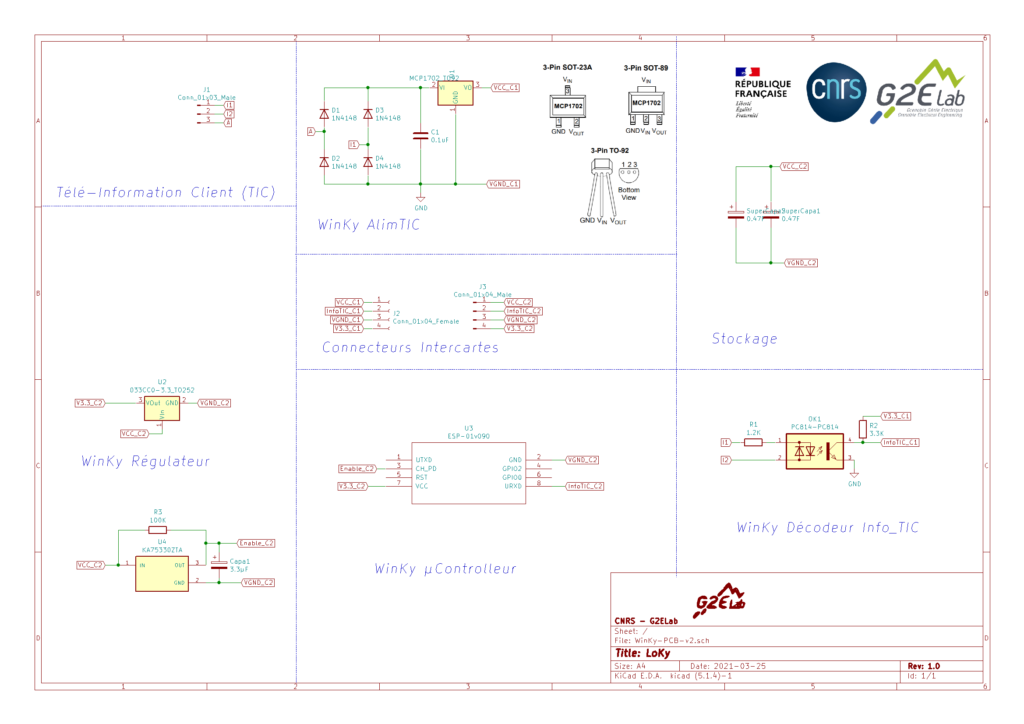
Here are the main components of WinKy:
| ESP01S | 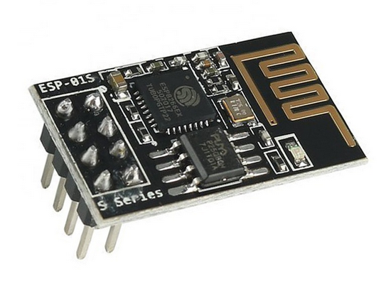 |
| Optocoupler PC814 | 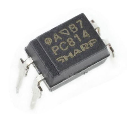 |
| 2 x 5.5V 0.5F super capacitors | 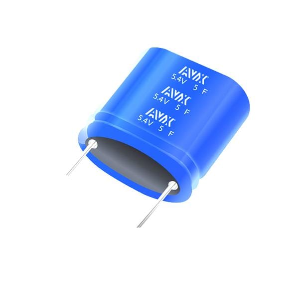 |
| 1 x 033CC0 3.3v regulator | 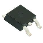 |
| 1 x MCP1702-4002E Voltage controller | 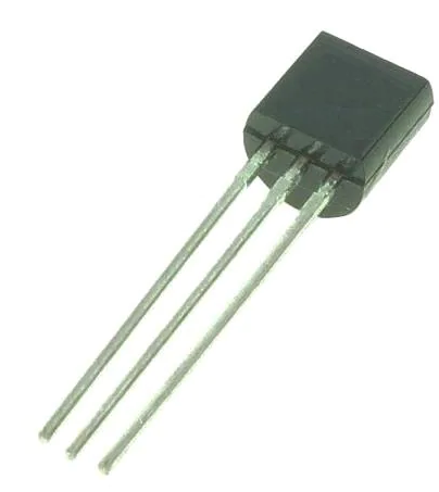 |
| 1 x KA75330 3.3V Voltage controller | 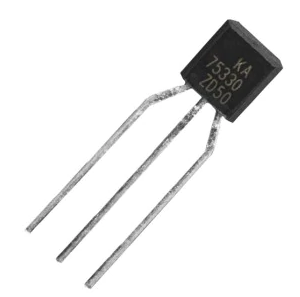 |
| 4 x 1n4148 diodes or equivalents | 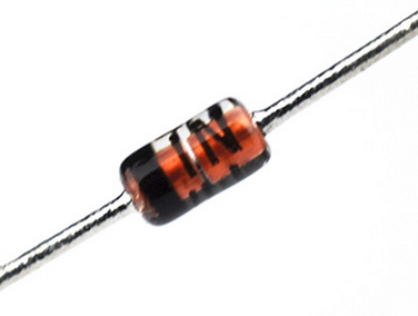 |
| 1 x 0.1µf capacitor | 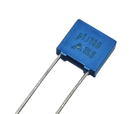 |
| 1 x 3.3µf electrolytic capacitor | 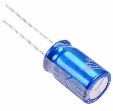 |
| 1 x 3.3kohms resistor | 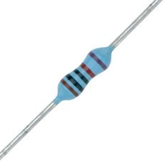 |
| 1 x 100kohms resistor | |
| 1 x 1.2kohms resistor | |
…you can find all these components in the schematic provided in the WinKy’ project’s GitLab repository.
IV. Prototyping of the different electronic stages
In this part, I follow essentially the same steps as seen in the previous version but I will focus on the energy optimization issue. https://miniprojets.net/index.php/2021/09/08/winky-open-source-projet-pour-linky-avec-wifi/embed/#?secret=b3lsDXT1GE
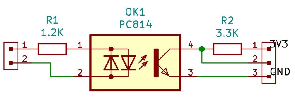
a. The decoding of InfoTIC
With all the specifications given by the datasheet, we must demodulate the ASK signals from InfoTIC. The most effective way is to take advantage of an optocoupler:
b. Energy storage with AlimTIC
This part is based on the work done on the Loky. However, Wi-Fi consumes more more energy as compared to Lora for transmission, it will therefore be necessary to add a super capacitor and play on the ESP01’s energy management strategy.
I also decoupled the power part from the teleinfo part at the power supply level because the ESP01 does not support more than 3.3V at the input.
c. Modification of the ESP01
For this part, I got a lot of help from the following sites:
http://frambooiseaupotager.blogspot.com/2019/09/tout-sur-le-deep-sleep-des-esp8266.html
https://www.instructables.com/Enable-DeepSleep-on-an-ESP8266-01/
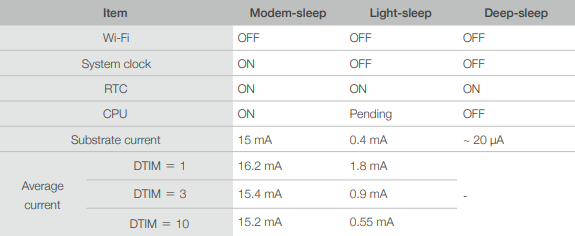
To sum things up, the big concern the ESP01’s consumption in the different stages of operation:
- When it wakes up the first time, the Wi-Fi is directly active and consumes a lot of energy.
- When the Wi-Fi is transmitting. The goal here is to put it in DeepSleep mode when the data transmission ends.
- The LED indicating its status lights up as soon as it starts up, consumes energy for nothing and in addition brought me a lot of problems ^^.
Here is a table showing the consumption in the different modes of the ESP01 extracted from the site http://frambooiseaupotager.blogspot.com/2019/09/tout-sur-le-deep-sleep-des-esp8266.html
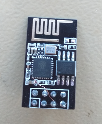
To put the device in DeepSleep, you must modify the ESP01 in order to take advantage of this function. This is the trickiest part because you have to solder pin 8 (XPD_DCDC) to the reset pin because this pin goes low when the ESP8266 goes into WakeUp mode.
So I suggest you follow this Instructables page:
https://www.instructables.com/Enable-DeepSleep-on-an-ESP8266-01/
And here is another site with more detailed explanations.
https://www.tech-spy.co.uk/2019/04/enable-deep-sleep-esp-01/embed/#?secret=OINAluCDb2
For me, the modification to allow deep sleep looks like this.
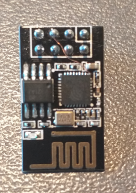
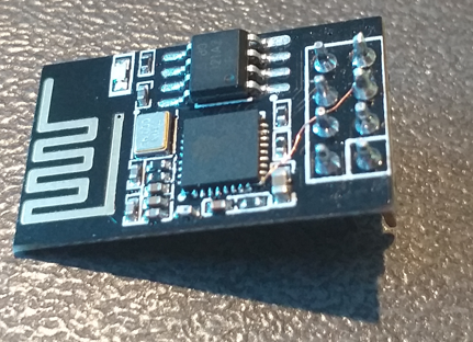
I also removed the LED
Now that everything is ok, we can move on to the data recovery part.
d. Energy monitoring and management
Not being a trained electronics engineer, this part was the one that posed the most problem to solve because it was necessary to find a balance between sending time, discharging time and cutting the power supply of the µcontroller.
For this, I had to make modifications on both the hardware and the software.
At the software level, my solution was based on the recommendations found here:
https://www.bakke.online/index.php/2017/05/21/reducing-wifi-power-consumption-on-esp8266-part-1/
https://www.bakke.online/index.php/2017/05/21/reducing-wifi-power-consumption-on-esp8266-part-2/
https://www.bakke.online/index.php/2017/05/21/reducing-wifi-power-consumption-on-esp8266-part-3/
and for the Hardware part, I used some information from this forum:
To sum up, the bulk of the work was to correctly configure the voltage control part and connect everything to the Enable pin of the ESP01 so that it only triggers its first wakeup when there is enough energy in the super capacitors.
For this, I used a KA75330 voltage controller coupled with a reset circuit assembly in order to give a delay before authorizing the Enable pin of the circuit.
e. Testing
To test if the modifications made to the Winky (V2) give the desired results, we will observe the different phases of life: (1- start-up, 2- in normal operation,3- simulate a power cut, 4- simulate power being restored)
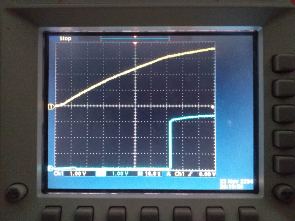
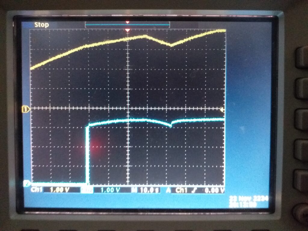
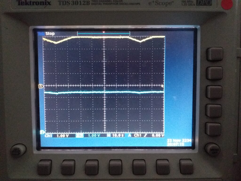
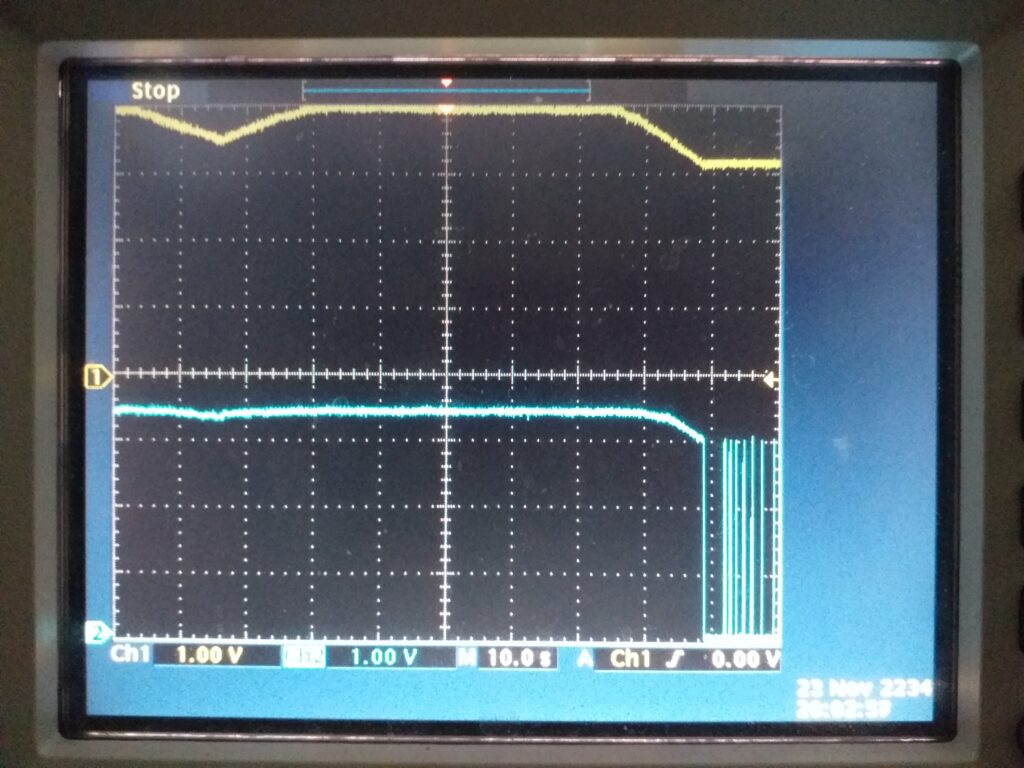
On the different oscilloscope captures, the yellow curve shows the voltage of the supercaps, the blue curve shows the signal on the Enable pin
First start
We can see that after 70s the super capacitors have accumulated enough energy to allow the µcontroller to start up and the program will execute the following instructions
- Wake
- turn off wifi
- Fall asleep for 30 seconds
After 30 seconds, the program will do the following steps:
- Wake up and turn wifi back on
- Read tick values
- Send data to MQTT broker
- Go back to sleep for 30 seconds and go back for a cycle
It takes about 12 seconds
Normal life stage
The program will loop through the same steps:
- Wake
- turn off wifi
- Fall asleep for 30 seconds
- Wake up and turn wifi back on
- Read tick values
- Send data to MQTT broker
- Go back to sleep for 30 seconds and go back for a cycle
Life phase when a power outage occurs
When a power outage occurs the program will continue to try to live normally, however, the voltage monitoring circuit will block the Enable pin and disable the µcontroller.
The rebounds that we observe are due to the effect of the supercaps which, as soon as they are no longer solicited, “regain” voltage and therefore re-authorize the Enable pin and so on. This phenomenon lasts only 15 seconds before stopping.
Power restoration phase
In this phase, we can see that the supercapacitors, thanks to the voltage control circuit, have not lost any energy (or very little because the assembly at this time only consumes 1µA) and only when restarting of the current the assembly returns normally.
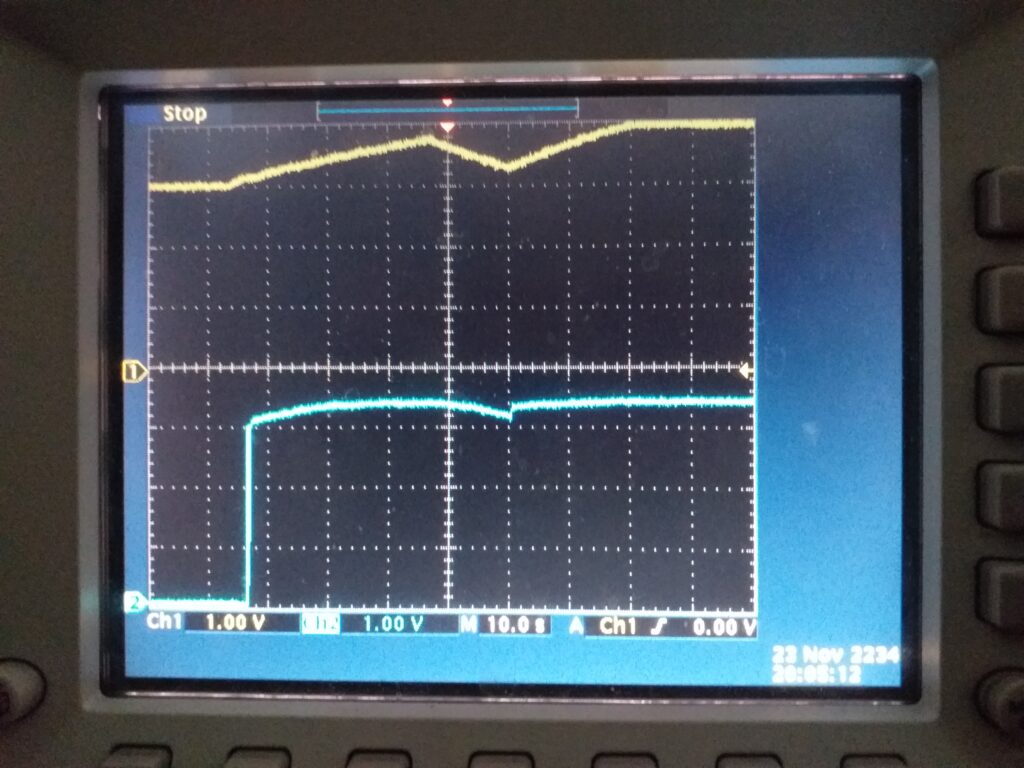
The next tests will aim to reduce the time between each sending of data.
f. The final diagram selected
In the end, the functional assembly is as depicted below:
Now that everything is ok, we can move on to the data recovery part.
V. MQTT Server + JEEDOM
For this part, if you have already read my previous articles, you become familiar with this part.
Come on a little reminder? For this, I invite you first to configure your raspberry or others with the following links:
Installation of Jeedom — > See my previous article https://miniprojets.net/index.php/2019/05/13/jeedom-ou-comment-domotiser-sa-maison-en-quelques-clics/
Installation of Mosquitto -> I recommend the following site https://projetsdiy.fr/jeedom-mqtt-objets-connectes-domotique-diy/
VI. LoKy Firmware
Before starting to program the ESP01, a small interface must be created or purchased.
I offer you this article which allows you to choose yours
https://projetsdiy.fr/esp01-quel-programmer-choisir-modification-activer-flash-mode/
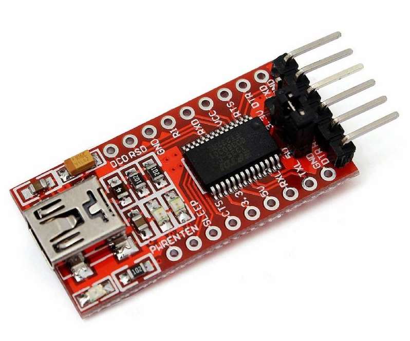
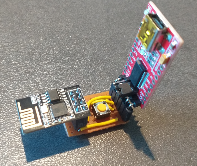
Or make your own if you already have a Mini-USB to TTL FT232RL adapter that we use to program the LoKy
For this you need:
- A 6×10 hole plate
- A female header of 1×6 pins
- A 2x4pin female header
- A push button
Then you have to connect the elements as follows:
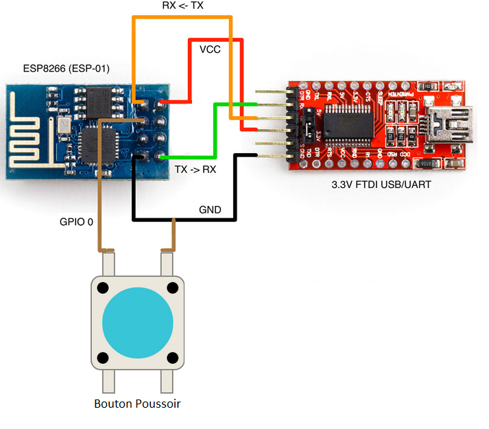
And what it actually looks like…. Good…. you can’t blame me for the cable monochrome ^^.
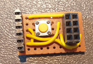
Now all that remains is to program it.
For this, I recommend you read this article and configure your Arduino IDE.
Once done, you can take the program that is on the Winky project repository:
https://gricad-gitlab.univ-grenoble-alpes.fr/ferrarij/winky
Then edit it to read:
- The SSID of your wifi network on which it will connect
- The password of your wifi network
- the IP address of your MQTT server
You can also add topics because in the present code, I only put the PAPP as an example
Once all that is done, you can flash it and put it in place.
VII. Installation and start-up of the WinKy
Attention, now that your Winky is programmed, you can set it up.
Now plug your WinKy into the Linky’s TIC socket.
Normally we are done for the installation part.
However, before closing the cover of your Linky, I advise you to wait because there may be adjustments to be made to the duration of DeepSleep. (Default set to 60 seconds).
It will be necessary to modify the line of code ESP.deepSleep(60000000); if you need to extend the cooldown of your Supercapa.
VIII. Checking that your WinKy is working properly
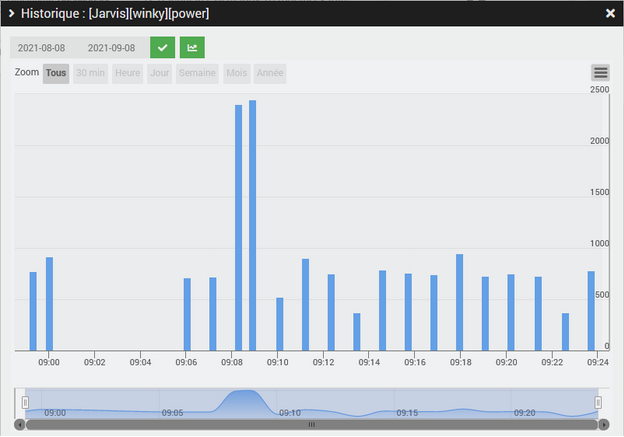
Normally, if everything works correctly, you will see your WinKy appear on your MQTT interface of your Jeedom

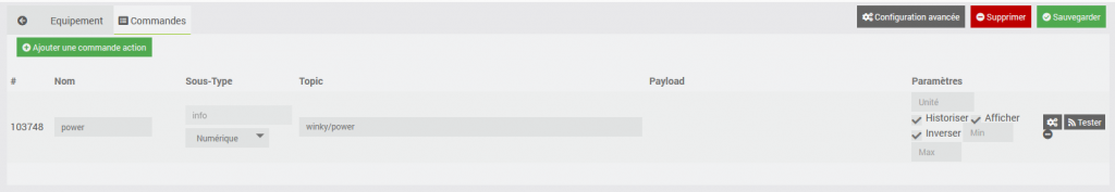
Check the Log box to see how often your counter data is uploaded.
I hope you have learned something and do not hesitate to send us your feedback as well as the problems you encounter, we appreciate your contribution to WinKy .
And see you soon for new articles and new sensors.
Jerome Ferrari