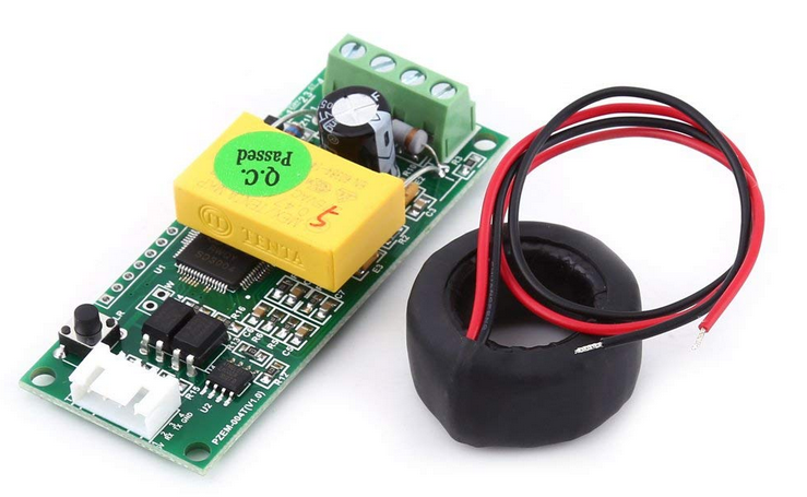
Using a Raspberry Pi 3 to get information of two PZEM004T sensors which are connected to the Arduino Mega microcontroller
21 août 2019Hi everyone,
Today and for the end of my internship, i propose this tutorial to connect raspberry pi and 2 Pzem004T together.
All the sources are CC-BY-NC-SA https://creativecommons.org/licenses/by-nc-sa/3.0/fr/

Brief description:
The aim of this article is to explain how to get the voltage, current and power measured by two PZEM 004T sensors from a Raspberry Pi 3. The sensors are not directly connected to the Raspberry but they are connected to an Arduino microcontroller (Mega 2560) and this is connected to the Raspberry via USB cable. We first get all these values by using the arduino microcontroller and then we send them to the Raspberry.

Procedure:
As stated before, the first step is to collect all the values from the Arduino microcontroller, so in order to do that we should use the library <PZEM004T.h>. This library can be downloaded from the webpage: https://github.com/olehs/PZEM004T as a zip package, then it should be added within the Arduino IDE as shown in the picture.

The next step is to connect the sensors to the arduino microcontroller. We will use the SoftwareSerial library to allow serial communication on other digital pins of the Arduino and be able to read more than one serial device. So, the RX and TX terminals of first sensor are connected to the pins 11 and 10 of the microcontroller and the RX and TX terminals of second sensor are connected to the pins 13 and 12 respectively.
Now, it is time to develop the code in Arduino IDE as follows:
/////////////////////////////////////////////////////////////////////////////////////////////////////////////////////////////////////////////// //* Code to get the voltage, current and power from two AC PZEM sensors connected to the Arduino Mega microcontroller, then all the values *// // are concatenated in one char variable in order to send it through serial communication // ///////////////////////////////////////////////////////////////////////////////////////////////////////////////////////////////////////////// #include#include IPAddress ip(192,168,1,11); IPAddress ip1(192,168,1,10); char ix[10]; char iy[10]; char iz[10]; char conc[360]; char ix1[10]; char iy1[10]; char iz1[10]; float V, V1; float i, i1; float p, p1; void setup() { Serial.begin (9600); } void loop() { PZEM004T pzem(10,11); //(RX TX) pzem.setAddress (ip); V=pzem.voltage(ip); //voltage obtained from the pzem library i = pzem.current(ip); //current obtained from the pzem library p = pzem.power(ip);//power obtained from the pzem library dtostrf(V,7,3,ix); //function used to stored the current value in the char variable ix, specifying 3 as the number of digits after the point dtostrf(i,7,3,iy); //function used to stored the current value in the char variable iy, specifying 3 as the number of digits after the point dtostrf(p,7,3,iz); //function used to stored the power value in the char variable iz, specifying 3 as the number of digits after the point delay(1000); PZEM004T pzem1(12,13); //(RX TX) pzem1.setAddress (ip1); V1=pzem1.voltage(ip1); //voltage obtained from the pzem library i1 = pzem1.current(ip1); //current obtained from the pzem library p1 = pzem1.power(ip1);//power obtained from the pzem library dtostrf(V1,7,3,ix1);//function used to stored the current value in the char variable ix1, specifying 3 as the number of digits after the point dtostrf(i1,7,3,iy1); //function used to stored the current value in the char variable iy1, specifying 3 as the number of digits after the point dtostrf(p1,7,3,iz1); //function used to stored the power value in the char variable iz1, specifying 3 as the number of digits after the point delay(1000); sprintf(conc,": %s, : %s, : %s, : %s, : %s, : %s,\n", ix,iy,iz,ix1,iy1,iz1); // function used to concatenate all the values in one unique char variable Serial.write(conc); }
Remarks:
- The sensors are not read at the same time.
- The type of the values given by the sensor is float.
- After getting all the values these are converted from float to char type by using the “dtostrf” function in which the decimal places are limited to three.
- All the 6 values are concatenated, using the function “sprintf”, in one unique char array and then it is sent as serial data.
- Besides putting all the values together in the char array, we also put the ‘:’ and ‘,’ characters. In the end, the char array looks like: “: val1, : val2, : val3, : val4, : val5, : val6, :”. It is done in order to analyze and get the values easily in python.
After uploading and testing the code on the microcontroller, it is time to deal with the python script. The Arduino microcontroller should be connected to the Raspberry by using a USB cable.
Before starting with the code, it could be good to know how to create a python file from the Linux terminal. It is done by typing the next command line:
touch PZEM_Sensors.py
Then to open the file already created, we should type the next command line:
nano PZEM_Sensors.py
The next screen will appear:

So now, let’s take a look at the code:
import serial
 import time
 import re

 port = "/dev/ttyACM0"
 s1 = serial.Serial(port,9600)

 while True:
     if s1.inWaiting()>0:
         inputValue = s1.readline().decode()
         m = re.search('.*:(.*),.*:(.*),.*:(.*),.*:(.*),.*:(.*),.*:(.*),',inputValue) # command used to read the information and split it between the charcaters ':' and ','
         v1 = m.group(1).replace(" ","") ## command used to saved the information splitted before in a the variable
         i1 = m.group(2).replace(" ","")
         p1 = m.group(3).replace(" ","")
         v2 = m.group(4).replace(" ","")
         i2 = m.group(5).replace(" ","")
         p2 = m.group(6).replace(" ","")
         a = float(v1)
         b = float(i1)
         c = float(p1)
         d = float(v2)
         e = float(i2)
         f = float(p2)
         print("Voltage1:",+a)
         print("Current1:",+b)
         print("Power1:",+c)
         print("Voltage2:",+d)
         print("Current2:",+e)
         print("Power2:",+f)
Remarks:
- We should specify the port of the Raspberry where the sensor is connected to. To know it, we should just type the next command from the LX Terminal window: ls /dev –> The names of the connected USB devices start with: “ttyUSBX”. Where X indicates the number of each USB device connected.
- The serial port is read and decoded to make sure we have a string of chars. It is done with the function readline() and decode() respectively.
- All the six values are getting by using regular expressions. Using ‘.*:(.*),’, we take all the characters which are between ‘:’ and ‘,’ and then they are stored in groups.
- In the end the values are converted from char to float type.
After writing all the code and pressing the keys Ctrl + X you will be asked to save it or not. You should press the key y or n and then Enter.
To run the code, we should type the next command line:
python PZEM_Sensors.py
Then all the results and messages will appear in the Terminal windows or a message of error will appear if something wrong is inside the code.
The figure below shows all the results got from the two PZEM sensors. The current 1 is 0 due to there is not any current sensor connected to and for that the reason the power 1 is also 0. If there is any problem of communication the value, we will get is -1.

I hope this tutorial can help you,
Best regards,
Richard Flores Diaz


I really appreciate your help with my project!
I would like to thank you for the efforts you have put in writing this site.
I’m hoping to check out the same high-grade
blog posts by you later on as well. In truth, your creative writing abilities has motivated me to get my own website now 😉
hello,
thanks for your example
I got ons question : why do you use ip adresse for the pzem_sensors ? can we use any sort of adress ? do we need to use real adresses usable our network ?
Thank you for your help
Sincerely
Jerome
Hello,
We use adresses because each PZEM004T device has an internal device address(Coded in the form of an IP Address but doesn’t need to conform, you can have 0.0.0.0 for example), which can be used to create a pseudo-master/slave bus, allowing to connect multiple devices to the same UART, thereby eliminating software serials.
In my exemple, we use 2 different buses to communicate with 2 PZEM but you can attach in the same bus a lot of PZEM.
The information of how to do that is here: https://github.com/xoseperez/espurna/wiki/Sensor-PZEM004T
The adress is a pseudo-adress you can’t connect directly your PZEM on a router.
I hope i replied correctly to your question.
BR,
Jérôme Ferrari
nice artilce , thank you . keep it up