NodeMcu ou comment piloter des prises via le Wifi pour moins de 10€
24 avril 2018Bonjour,
Aujourd’hui, on va étudier la problématique d’alimenter ou d’éteindre des prises à distance via un réseau Wifi.
Pour information, Les sources sont CC-BY-NC-SA https://creativecommons.org/licenses/by-nc-sa/3.0/fr/

Les objectifs secondaires sont un pilotage via un site web, une solution coutant moins de 10€ et peu gourmande en énergie.
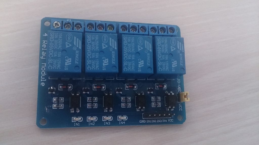
J’ai donc décidé de partir sur une solution basée sur un nodeMcu (ESP8266) et de relais.
Personnellement, j’ai acheté un lot de nodeMcu v3 sur aliexpress. Idem pour les relais.
Pour cette utilisation, j’ai acheté 1 module relais comprenant 4 relais car je n’ai que 3 prises et 1 lampe à gérer.

Bon, maintenant passons aux choses sérieuses…
Pour commencer, je passe par l’IDE d’arduino pour faire la programmation.
Dans un premier temps, il faut commencer par déclarer la board dans l’IDE.
Aller dans les préférences de votre IDE puis dans URL de gestionnaire de cartes supplémentaires et coller le lien suivant:
http://arduino.esp8266.com/stable/package_esp8266com_index.json
Cliquer ensuite sur OK.
Ensuite aller dans Outils -> Type de cartes -> Gestionnaire de carte
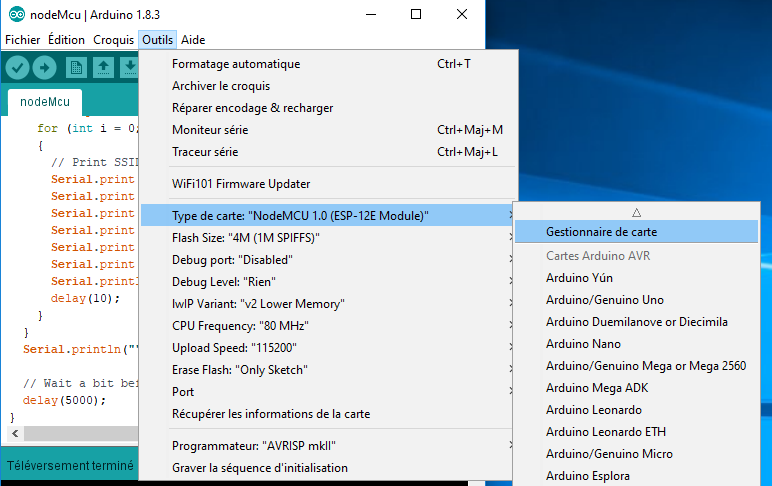
Rechercher esp8266 puis installer.
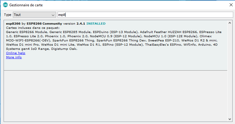
Une fois que cela est fait, cliquer sur OK.
Vous pouvez maintenant connecter votre NodeMcu sur l’ordinateur.
Pour ma part, j’ai dû installer les drivers CH340G pour le faire fonctionner.
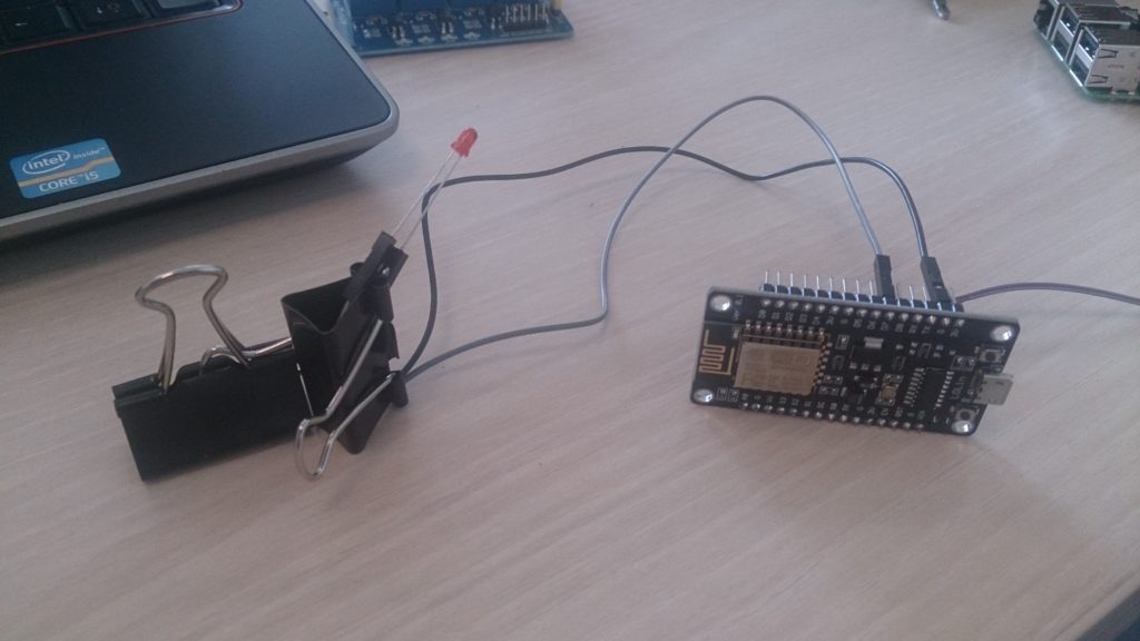
Maintenant que tout est ok, nous allons tester le fonctionnement de la carte.
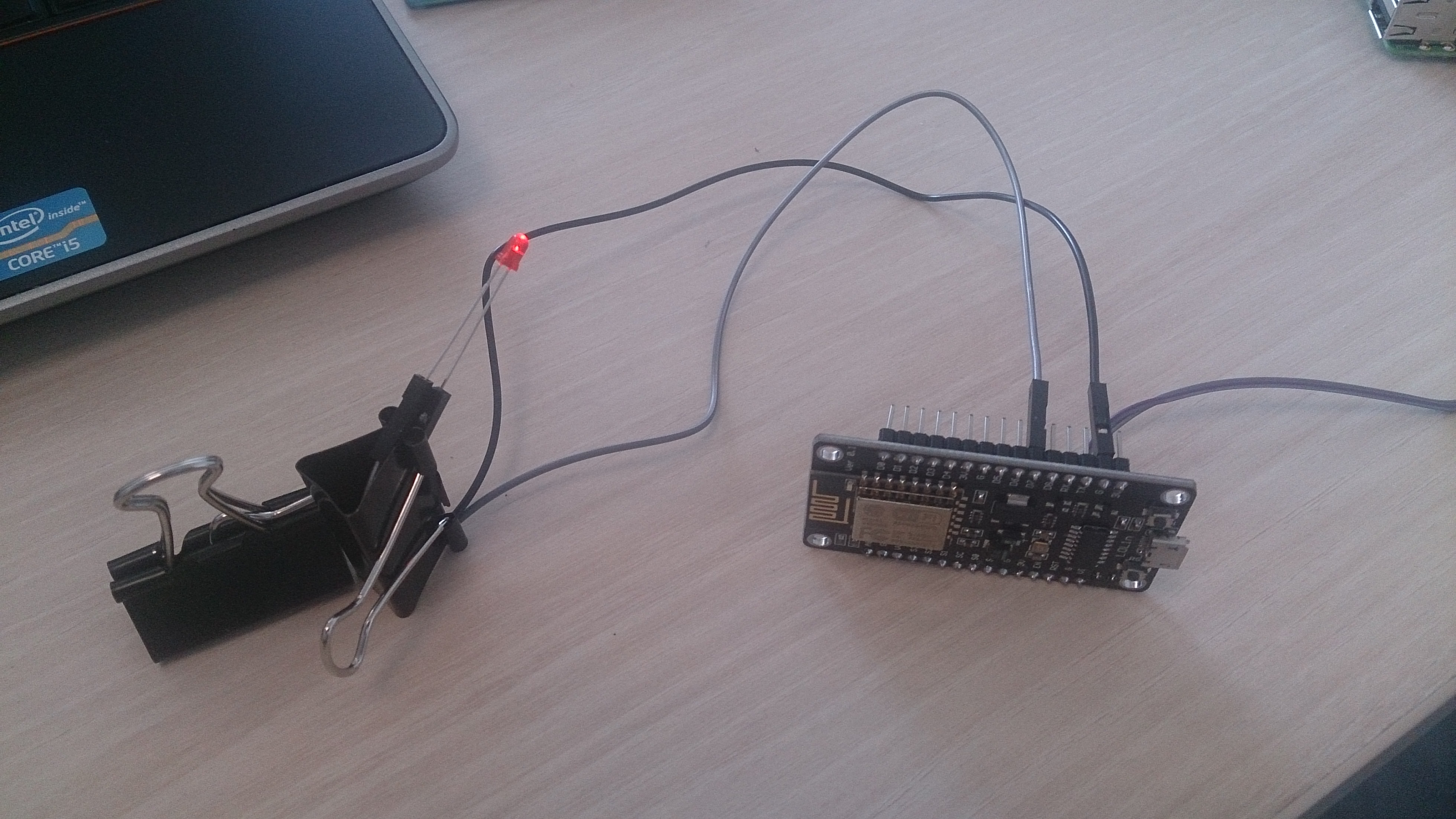
Pour cela, je vais utiliser une LED connectée directement au GND et à la pin D7 (qui correspond à la pin 13 pour un arduino)
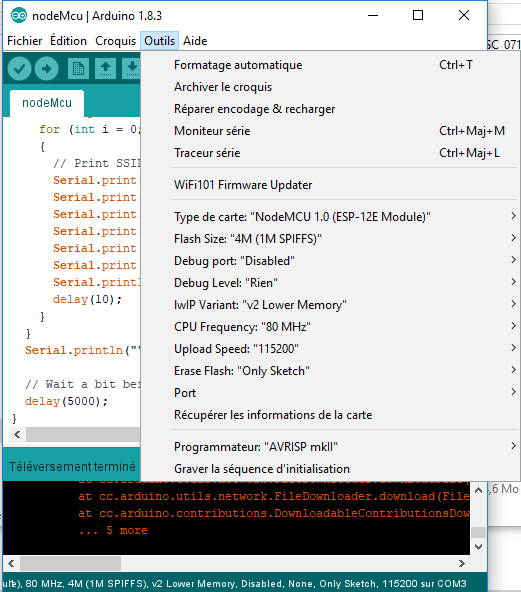
Pour les paramètres de communication dans l’IDE, j’ai mis ceux-ci:
Et pour le programme, j’ai utilisé ce code pour faire un test:
// Blink

// the setup function runs once when you press reset or power the board
void setup() {
  // initialize Pin D7 or digital pin 13 as an output.
  pinMode(13, OUTPUT);
}

// the loop function runs over and over again forever
void loop() {
  digitalWrite(13, HIGH);   // turn the LED on
  delay(1000);              // wait for a second
  digitalWrite(13, LOW);    // turn the LED off
  delay(1000);              // wait for a second
}
Une fois l’upload effectué la LED doit se mettre à clignoter.
Maintenant, nous allons passer à la partie « Site WEB ».
Il s’agira d’une interface HTML des plus basique.
Dans un premier temps, on va vérifier que le NodeMcu voit bien les réseaux Wifi.
Pour cela, j’utilise le code suivant:
#include "ESP8266WiFi.h"

void setup() {
  Serial.begin(115200);
  // Set WiFi to station mode and disconnect from an AP if it was previously connected
  WiFi.mode(WIFI_STA);
  WiFi.disconnect();
  delay(2000);
  Serial.println("Setup done");
}

void loop() {
  Serial.println("scan start");


  int n = WiFi.scanNetworks();// WiFi.scanNetworks will return the number of networks found
  Serial.println("scan done");
  if (n == 0)
    Serial.println("no networks found");
  else
  {
    Serial.print(n);
    Serial.println(" networks found");
    for (int i = 0; i < n; ++i)
    {
      // Print SSID and RSSI for each network found
      Serial.print(i + 1);
      Serial.print(": ");
      Serial.print(WiFi.SSID(i));
      Serial.print(" (");
      Serial.print(WiFi.RSSI(i));
      Serial.print(")");
      Serial.println((WiFi.encryptionType(i) == ENC_TYPE_NONE)?" ":"*");
      delay(10);
    }
  }
  Serial.println("");

  // Wait a bit before scanning again
  delay(5000);
}
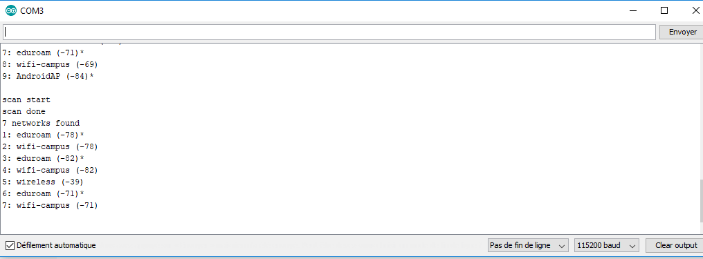
Une fois téléchargé dans le NodeMcu, on ouvre le moniteur série. Normalement, on doit voir les réseaux qui nous entourent comme dans l’exemple ci-dessous.
Maintenant que l’on voit les réseaux wifi et que l’on sait contrôler une LED… On va mixer tout cela pour contrôler une LED via un site Web!!!
Pour cela, j’utilise le code suivant:
#include <ESP8266WiFi.h>

// set wifi IDs
const char* ssid = "wireless";
const char* password = "password";

// attach led to pin 13
int ledPin = 13; // GPIO13
WiFiServer server(80);

void setup() {
  Serial.begin(115200);
  delay(10);

  pinMode(ledPin, OUTPUT);
  digitalWrite(ledPin, LOW);

  // Connect to WiFi network
  Serial.println();
  Serial.println();
  Serial.print("Connecting to ");
  Serial.println(ssid);

  WiFi.begin(ssid, password);

  while (WiFi.status() != WL_CONNECTED) {
    delay(500);
    Serial.print(".");
  }
  Serial.println("");
  Serial.println("WiFi connected");

  // Start the server
  server.begin();
  Serial.println("Server started");

  // Print the IP address
  Serial.print("Use this URL to connect: ");
  Serial.print("http://");
  Serial.print(WiFi.localIP());
  Serial.println("/");

}

void loop() {
  // Check if a client has connected
  WiFiClient client = server.available();
  if (!client) {
    return;
  }

  // Wait until the client sends some data
  Serial.println("new client");
  while(!client.available()){
    delay(1);
  }

  // Read the first line of the request
  String request = client.readStringUntil('\r');
  Serial.println(request);
  client.flush();

  // Match the request

  int value = LOW;
  if (request.indexOf("/LED=ON") != -1)  {
    digitalWrite(ledPin, HIGH);
    value = HIGH;
  }
  if (request.indexOf("/LED=OFF") != -1)  {
    digitalWrite(ledPin, LOW);
    value = LOW;
  }

// Set ledPin according to the request
//digitalWrite(ledPin, value);

  // Return the response
  client.println("HTTP/1.1 200 OK");
  client.println("Content-Type: text/html");
  client.println(""); //  do not forget this one
  client.println("<!DOCTYPE HTML>");
  client.println("<html>");

  client.print("Led pin is now: ");

  if(value == HIGH) {
    client.print("On");
  } else {
    client.print("Off");
  }
  client.println("<br><br>");
  client.println("<a href=\"/LED=ON\"\"><button>Turn On </button></a>");
  client.println("<a href=\"/LED=OFF\"\"><button>Turn Off </button></a><br />");
  client.println("</html>");

  delay(1);
  Serial.println("Client disonnected");
  Serial.println("");

}
Une fois l’upload terminé, on ouvre le terminal pour connaitre l’adresse IP du NodeMcu.
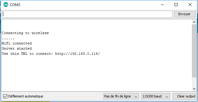
Nous pouvons donc aller sur un navigateur et on tape l’URL donnée. On peux enfin jouer avec les boutons et voir la LED s’allumer et s’éteindre.
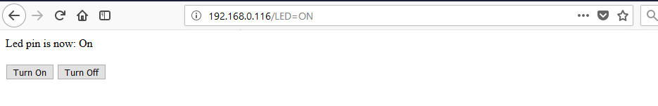
On peut même récupérer l’état des actions via le moniteur série
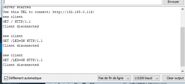
Et voila maintenant on sait piloter une LED via le Wifi!
Pour le reste, il suffit d’adapter le code afin de piloter le module relais et de connecter le tout sur une source de 5V!
Mon code et une photo de l’installation arrivent bientôt…
Les sources pour cet article sont:
https://www.hackster.io/Aritro/getting-started-with-esp-nodemcu-using-arduinoide-aa7267
https://ouiaremakers.com/posts/tutoriel-diy-un-capteur-de-temperature-humidite-en-wifi-avec-une-page-web
@Bientôt
Ferrader